Kubota ignition switch wiring diagrams are essential for troubleshooting, repairs, and customization of tractor electrical systems, guiding users through circuits and connections for proper functionality.
Overview of the Importance of Wiring Diagrams
Wiring diagrams are crucial for understanding and working with Kubota ignition systems, providing a clear visual representation of electrical circuits. They aid in troubleshooting, repairs, and customization, ensuring proper installation and maintenance. These diagrams help diagnose issues quickly and safely, making them indispensable for technicians and DIY enthusiasts alike.
Common Applications of Kubota Ignition Switch Diagrams
Kubota ignition switch diagrams are widely used for diagnosing faulty ignition systems, planning custom electrical setups, and ensuring safe repairs. They also assist in upgrading or replacing components, such as starters and fuses, and guide technicians in maintaining tractor performance and reliability, making them a vital resource for both professionals and enthusiasts.

Key Components of a Kubota Ignition Switch Wiring Diagram
A Kubota ignition switch wiring diagram includes the ignition switch, starter motor, fuse systems, wiring harness, and connectors, ensuring proper electrical flow for engine operation.
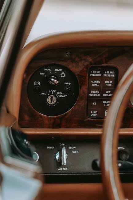
The Ignition Switch and Its Functions
The ignition switch acts as the central control unit, managing the tractor’s electrical system. It powers the ignition coil, starter motor, and accessories, while ensuring safety by disconnecting the circuit when the engine is off, preventing unauthorized use and electrical hazards.
The Starter Motor and Its Connection
The starter motor is connected to the ignition switch through a wiring harness, with the solenoid acting as an intermediary. When the ignition switch is activated, it sends a signal to the solenoid, which then engages the starter motor, allowing the engine to crank. Proper wiring connections ensure reliable starting and prevent electrical issues.
Fuse and Relay Systems in Kubota Tractors
Fuse and relay systems in Kubota tractors protect electrical circuits from overloads. Fuses like T1 (25A) and T2 (25A) are strategically placed to interrupt power in case of a short circuit. Relays, such as the starter relay, amplify signals to control high-current components like the starter motor. Proper maintenance ensures reliable operation and prevents electrical failures, keeping the tractor running smoothly and safely.
Understanding the Kubota Wiring Harness
The Kubota wiring harness is a critical component, organizing and protecting electrical circuits; It connects components like the ignition switch, starter motor, and fuses, ensuring reliable power distribution and signal transmission across the tractor’s systems.
Color Coding and Wire Identification
Color coding in Kubota wiring diagrams is crucial for wire identification. For instance, yellow/red wires typically connect to ignition switches, while black wires are often ground connections. This systematic approach ensures technicians can quickly trace circuits, diagnose issues, and perform repairs efficiently. Consistent color coding across diagrams simplifies maintenance and reduces the risk of electrical errors.
Connectors and Terminals in the Harness
Kubota wiring harnesses utilize standardized connectors and terminals to ensure reliable electrical connections. Key components include 16-pin connectors for ignition switches and sealed terminals to prevent corrosion. Properly matching connectors to terminals is critical for maintaining circuit integrity. Always refer to the diagram for accurate pin assignments and connections to avoid system malfunctions during repairs or upgrades.

Safety Features in Kubota Ignition Systems
Kubota ignition systems include essential safety features like starter safety switches, oil pressure switches, and fuses to prevent malfunctions and ensure operator safety during tractor operation.
Starter Safety Switch (Clutch Switch)
The starter safety switch, often linked to the clutch, ensures the engine starts only when the clutch is disengaged, preventing accidental starts. It connects to the ignition circuit, acting as a critical safety feature. Proper wiring, as shown in diagrams, is essential for its function. Testing involves checking continuity and ensuring it aligns with safety protocols for reliable tractor operation.
Oil Pressure Switch and Its Role
The oil pressure switch monitors engine lubrication, ensuring adequate oil pressure. If levels drop, it triggers warnings or shuts down the engine to prevent damage. In wiring diagrams, it’s connected to the ignition system and warning lights, providing critical feedback for tractor operation and maintenance, as detailed in Kubota manuals and PDF guides online.
How to Read a Kubota Ignition Switch Wiring Diagram
Understanding symbols, color coding, and tracing circuits are key to interpreting Kubota wiring diagrams. This process aids in diagnosing issues and customizing tractor electrical systems effectively.
Identifying Symbols and Abbreviations
In Kubota wiring diagrams, symbols represent components like ignition switches, fuses, and relays. Abbreviations such as “IGN” for ignition and “ACC” for accessory simplify the layout. Understanding these symbols and abbreviations is crucial for accurately tracing circuits and diagnosing electrical issues in Kubota tractors. Always refer to the provided legend for clarity and precision in repairs or modifications.
Tracing Circuits and Connections
Tracing circuits in Kubota ignition wiring diagrams involves following the flow of electricity from the ignition switch through components like fuses, relays, and the starter motor. Use symbols and color codes to identify connections. Start at the ignition switch, track power distribution, and verify ground connections. This method ensures accurate troubleshooting and proper system functionality in Kubota tractor electrical systems.
Troubleshooting Common Issues
Troubleshooting Kubota ignition issues involves identifying short circuits, faulty switches, and failed components. Use wiring diagrams to trace circuits and test components for proper function.
Identifying Short Circuits and Faults
Identifying short circuits in Kubota ignition systems involves checking for blown fuses, unusual wire connections, and erratic power flows. Consult wiring diagrams to trace circuits, ensuring all components function correctly. Use multimeters to test resistance and voltage, pinpointing faults like damaged wires or malfunctioning switches.
Testing the Ignition Switch and Related Components
Testing the Kubota ignition switch involves using a multimeter to check for continuity and voltage drops. Verify the switch’s terminals for proper connections and ensure the starter motor engages when activated. Inspect related components like fuses, relays, and wiring for damage or corrosion. Replace any faulty parts to restore system functionality and prevent further issues.
Downloading and Using Kubota Wiring Diagram PDFs
Kubota wiring diagram PDFs are readily available online, offering detailed schematics for ignition systems and tractor models like B1600 and M9540. Download from official Kubota websites or forums for accurate and clear guidance on electrical circuits and components.
Locating Genuine Kubota Manuals Online
Genuine Kubota manuals, including wiring diagrams for ignition switches, can be found on official Kubota websites, authorized dealers, or trusted forums. Ensure authenticity by verifying sources and document versions, as counterfeit manuals may provide incorrect information. Always download PDFs from reputable platforms to guarantee accuracy and compatibility with your specific tractor model.
Using PDF Tools for Effective Diagram Analysis
PDF tools like Adobe Acrobat enable detailed analysis of Kubota ignition switch wiring diagrams. Users can zoom in for clarity, search for specific components, and bookmark sections for easy navigation. These tools enhance understanding and troubleshooting by providing interactive features, ensuring compatibility with genuine Kubota manuals for accurate repairs and maintenance.
Kubota Ignition Switch Parts List
Kubota ignition systems include essential components like the ignition switch, starter motor, fuses, relays, and connectors, ensuring reliable electrical connections for tractor operation and performance.
Essential Components and Their Specifications
Kubota ignition systems include the ignition switch, starter motor, fuses, relays, and wiring harness. These components are designed for durability and compatibility, ensuring proper electrical connections. The ignition switch is rated for 12VDC, while fuses and relays protect the circuit from overloads. The wiring harness features color-coded wires for easy identification, ensuring reliable performance in Kubota tractors.
Compatible Replacement Parts and Accessories
Kubota ignition systems require genuine or compatible parts for optimal performance. Replacement ignition switches, fuses, and wiring harnesses are available, ensuring seamless integration. Accessories like connectors and terminals are also essential for maintaining electrical integrity. Always refer to Kubota manuals or official suppliers to ensure compatibility and avoid installation issues, guaranteeing reliable tractor operation and longevity of the ignition system.
DIY Tips for Kubota Ignition System Maintenance
Regularly inspect wiring for damage or corrosion, clean connections, and test components using a multimeter. Replace worn parts promptly to prevent system failures and ensure reliable operation.
Best Practices for Circuit Inspection
Begin by disconnecting the battery to ensure safety. Use a multimeter to test voltage and resistance across circuits. Inspect wires for frays or damage, and clean connectors to prevent corrosion. Refer to the Kubota wiring diagram to trace circuits accurately, ensuring all components function as specified. Replace any faulty parts immediately to maintain system reliability and performance.
Preventative Maintenance to Avoid Failures
Regularly inspect wiring for wear, corrosion, or damage. Clean connectors to prevent poor connections. Test fuses and relays annually, replacing as needed. Check the ignition switch for smooth operation and ensure proper voltage levels. Follow Kubota’s recommended maintenance schedule to avoid unexpected system failures. Use genuine parts and consult wiring diagrams for accurate repairs and upgrades.
Kubota ignition switch wiring diagrams are invaluable for diagnostics and repairs. Always use genuine manuals, follow best practices, and consult resources for reliable tractor maintenance and upgrades.
Final Tips for Working with Kubota Wiring Diagrams
- Always refer to genuine Kubota manuals for accurate diagrams and specifications.
- Test ignition switches and related components before replacing them.
- Use color coding to identify wires and ensure proper connections.
- Verify ground connections for optimal system performance.
- Consult online forums or experts for additional troubleshooting guidance.
- Perform regular inspections to prevent electrical system failures.
Resources for Further Assistance
For detailed guidance, refer to genuine Kubota manuals and official websites offering PDF downloads. Online forums like GeoHorn provide valuable insights and shared experiences. Specific models, such as the Kubota B1600 and M9540, have dedicated wiring diagrams available. Additionally, online marketplaces and repair shops often provide downloadable resources and expert assistance for troubleshooting and repairs.