
Club Car 48 Volt Wiring Diagram: A Comprehensive Guide
This manual streamlines setup and usage of your 1995 Club Car 48V system, offering clear instructions and illustrations for compatible accessories, ensuring a smooth experience.
Club Car’s 48-volt electrical systems represent a significant advancement in golf car technology, offering increased power, efficiency, and reliability compared to older 36-volt models. These systems are commonly found in models from 1995 onwards, becoming the industry standard for many years. Understanding the fundamentals of these systems is crucial for both routine maintenance and troubleshooting any potential electrical issues.
The transition to 48 volts necessitated changes in component design, including the motor, controller, and solenoid. A comprehensive wiring diagram is therefore essential for navigating the intricacies of this setup. This guide aims to demystify these systems, providing a clear pathway to understanding how each component interacts. Accessing a Club Car 48V wiring diagram PDF is the first step towards successful maintenance and repair, allowing you to confidently diagnose and resolve electrical problems.
Properly utilizing these diagrams ensures safe and effective work on your vehicle.
Understanding the Importance of Wiring Diagrams
A Club Car 48V wiring diagram PDF isn’t merely a technical illustration; it’s the roadmap to understanding and maintaining your vehicle’s electrical heart. These diagrams visually represent the complex network of wires, connectors, and components, enabling accurate diagnosis of faults and safe, effective repairs. Without a diagram, troubleshooting becomes a process of guesswork, potentially leading to further damage or even safety hazards.
Wiring diagrams are particularly vital when dealing with 48-volt systems due to their increased complexity. They detail the flow of electricity, identifying each component’s role and its connection to the overall system. A clear understanding of these connections allows for pinpointing issues like a faulty solenoid, a malfunctioning controller, or a damaged wiring harness.
Accessing the correct, year-specific diagram is paramount for accurate work.

Key Components & Their Functions
Understanding the core elements—motor, controller, battery pack, solenoid, and charger—is crucial for interpreting the 48V wiring diagram and effective system maintenance.
The Electric Motor
The electric motor is the heart of your Club Car’s drivetrain, converting electrical energy from the battery pack into mechanical power to drive the wheels. In a 48-volt system, the motor typically receives power through the controller and solenoid, initiating movement.
Understanding the motor’s wiring connections is vital when referencing a wiring diagram. Key connections include the armature (often larger gauge wires) and the field windings. A faulty motor can manifest as a lack of power, erratic speed, or unusual noises.
When troubleshooting, always check the motor brushes for wear and ensure proper continuity. The wiring diagram will illustrate the specific connections for your Club Car model year, aiding in accurate diagnosis and repair. Proper motor function relies on a correctly wired and functioning system.
The Controller
The controller acts as the brain of the electrical system, regulating the flow of power from the battery pack to the electric motor. It interprets signals from the accelerator pedal, dictating the speed and direction of the Club Car. A 48-volt controller manages the high voltage, ensuring safe and efficient operation.
The wiring diagram highlights the controller’s numerous connections, including battery positive and negative, motor leads, throttle input, and safety interlock circuits. Identifying these connections is crucial for troubleshooting. Common controller issues include blown fuses, faulty internal components, or damaged wiring harnesses.
Diagnostic procedures often involve checking voltage levels and continuity. A malfunctioning controller can cause a no-start condition, limited speed, or erratic performance. Always consult the specific wiring diagram for your Club Car model to ensure correct diagnosis and repair;
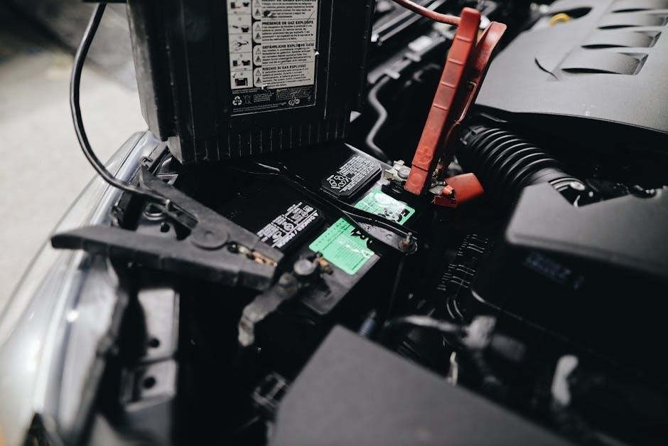
The Battery Pack (6x8V or 4x12V)
The battery pack provides the necessary power for the Club Car’s operation, typically configured as six 8-volt or four 12-volt batteries connected in series to achieve a total of 48 volts. Maintaining a fully charged and properly connected battery pack is vital for optimal performance and range.

The wiring diagram illustrates the series connection, showing how the positive terminal of one battery connects to the negative terminal of the next. Proper connection order is critical; reversing polarity can cause severe damage. Regular inspection for corrosion, loose connections, and individual battery health is essential.
Testing the battery pack’s voltage and individual battery voltages helps identify weak or failing batteries. Replacement should be done with batteries of the same type and capacity. Always follow safety precautions when working with batteries, as they contain corrosive acid.
The Solenoid
The solenoid acts as a heavy-duty switch, controlled by the accelerator pedal, to deliver high-current power from the battery pack to the electric motor. It’s a crucial component in the Club Car’s drive system, enabling operation when the pedal is depressed and disconnecting power when released.
The wiring diagram clearly depicts the solenoid’s connections, including the battery positive terminal, the motor, and the control signal from the accelerator pedal. A faulty solenoid can prevent the cart from moving or cause intermittent operation. Common issues include burnt contacts or a failed coil.
Testing the solenoid involves checking for continuity through the coil and verifying proper switching action. Replacement is relatively straightforward, but ensure the new solenoid matches the original specifications. Always disconnect the battery pack before working on the solenoid for safety.
The Charger & Charging System
The charging system is vital for maintaining battery health and ensuring optimal performance of your Club Car. Typically, a 48-volt system utilizes an off-board charger, connected to a charging receptacle on the vehicle. The wiring diagram illustrates the path from the receptacle to the battery pack, including any fuses or charge controllers.
Modern chargers employ sophisticated algorithms to prevent overcharging and maximize battery lifespan. Understanding the charger’s indicator lights is crucial for monitoring the charging process. Common issues include a faulty charger, damaged charging receptacle, or corroded connections.
Regularly inspect the charging cable and receptacle for damage. Always follow the manufacturer’s instructions for charging procedures. A properly functioning charging system is essential for reliable operation and longevity of your Club Car’s battery pack.

Decoding the Wiring Diagram
Successfully interpreting the diagram requires understanding color codes, key connectors, and schematic symbols, enabling accurate tracing of electrical paths within the system.
Color Coding Conventions
Understanding Club Car’s color coding is crucial for accurate diagnosis and repair. Typically, black wires represent the negative (-) or ground connection, serving as the return path for electrical current throughout the 48-volt system; Red wires commonly indicate the positive (+) connection, directly linked to the battery pack’s power source.
White or blue wires often signify control signals, transmitting commands from the controller to components like the solenoid or motor. Yellow wires frequently denote accessory power, supplying energy to lights, horns, and other features. However, variations exist between model years, so always verify with a specific diagram.
Orange wires can indicate charging circuit connections, relating to the battery charging system. Gray or brown wires may be used for instrumentation, connecting to the speedometers or voltage gauges. Always double-check the diagram, as color coding isn’t universally consistent and can change.
Identifying Key Connectors
Locating and understanding key connectors is vital when navigating a Club Car 48V wiring diagram. The main battery pack connector, often a large, multi-pin connector, supplies power to the entire system. The controller connector, typically rectangular, interfaces with the motor, throttle, and other control components.
Solenoid connectors, usually heavy-duty, manage high-current flow to the motor. Motor connectors, varying in size and shape, deliver power for propulsion. Charger connectors, specific to the charging system, facilitate battery replenishment.
Accessory connectors, smaller and diverse, power lights, horns, and other features. Pay close attention to connector orientation and pin assignments, as incorrect connections can cause damage. Diagrams clearly illustrate connector locations and wiring configurations; referencing them is essential for accurate identification and troubleshooting.
Understanding Schematic Symbols
Decoding schematic symbols is crucial for interpreting a Club Car 48V wiring diagram. A straight line represents a wire, while dashed lines indicate signal or control circuits. Circles denote connection points, and rectangles symbolize components like resistors or diodes.
The battery symbol depicts the power source, while the motor symbol illustrates the electric motor. A solenoid is often shown as a switch, and the controller as a complex integrated circuit. Ground symbols, typically represented by three descending lines, indicate the chassis ground.
Fuses are shown as a broken line within a rectangle, and connectors are depicted as interlocking circles. Familiarizing yourself with these symbols allows you to trace circuits, identify components, and understand the flow of electricity within the system, enabling effective troubleshooting.

Common Wiring Issues & Troubleshooting
Diagnosing electrical faults requires a systematic approach, utilizing the wiring diagram to pinpoint issues like faulty solenoids, controller malfunctions, or battery pack problems.
Faulty Solenoid Symptoms & Repair
A failing solenoid often presents as a “click” but no forward or reverse motion, indicating it isn’t fully engaging the motor. This crucial component acts as a heavy-duty switch, connecting the battery pack to the motor controller. Testing involves using a multimeter to check for voltage at the solenoid terminals when the pedal is depressed; absence of voltage suggests a faulty controller or wiring issue before the solenoid.
Repair typically involves solenoid replacement, ensuring the new unit matches the original’s specifications (voltage and amperage). Before disconnecting the old solenoid, carefully note the wiring configuration – a photograph is highly recommended! Disconnect the battery pack before any work begins. After installation, double-check all connections for tightness and proper polarity. A properly functioning solenoid should produce a distinct “clunk” when activated, confirming engagement.
Remember to consult the 48V wiring diagram to accurately identify the solenoid’s location and associated wiring.
Controller Problems & Diagnostics
Controller issues often manifest as erratic speed, lack of power, or complete failure to move. Unlike a simple solenoid click, controller failures can be subtle. Initial diagnostics require a thorough review of the 48V wiring diagram to verify all connections to the controller are secure and undamaged. Use a multimeter to check input voltage from the battery pack and output voltage to the motor – discrepancies indicate a potential controller fault.
Many controllers have diagnostic LEDs that blink in specific patterns to indicate error codes; consult the service manual for decoding these. Testing the throttle signal is also crucial, ensuring the controller receives the correct input from the pedal. Replacement often requires programming the new controller to match the vehicle’s specific configuration.
Always disconnect the battery pack before working on the controller, and exercise caution as some components can hold a charge even when disconnected.
Battery Pack Issues & Testing
A failing battery pack is a common cause of performance issues in a Club Car 48V system. Symptoms include reduced range, slow acceleration, and eventual stall. Referencing the 48V wiring diagram is essential to understand the pack’s configuration (6x8V or 4x12V) and connection points. Individual battery testing is crucial; use a battery hydrometer to check the specific gravity of each cell, indicating its state of charge and health.
Voltage testing under load provides a more accurate assessment. A significant voltage drop during acceleration suggests weak batteries. Inspect all battery cables and connections for corrosion or looseness, as these can impede current flow. Remember to charge all batteries fully before testing.
Replacing batteries should be done as a complete pack to ensure balanced performance and prevent premature failure of new batteries.
Motor Troubleshooting
Motor issues often manifest as a lack of power, unusual noises, or overheating. Begin by consulting the Club Car 48V wiring diagram to verify proper connections to the motor. Check the motor brushes for wear; excessive wear reduces contact and performance. Inspect the armature for shorts or open circuits using a multimeter – the wiring diagram will help identify test points.
A faulty motor controller can mimic motor problems, so rule that out first. Listen for bearing noise, which indicates internal damage. Verify the motor is receiving the correct voltage from the controller. If the motor spins freely with no load but fails under load, it suggests a field winding issue.
Always disconnect the battery pack before performing any motor testing or repairs to prevent electrical shock.
Wiring Harness Damage & Repair
Damage to the wiring harness is common in golf carts, often due to vibration, abrasion, or environmental exposure. Utilize the Club Car 48V wiring diagram to trace circuits and pinpoint damaged sections. Look for cracked insulation, corroded connectors, and broken wires. A visual inspection is crucial.
Repairing damaged wires involves stripping, splicing, and insulating. Use heat-shrink tubing with adhesive lining for a waterproof seal. Ensure splices are mechanically strong and electrically sound. Replace corroded connectors with new ones, applying dielectric grease to prevent future corrosion.
If damage is extensive, consider replacing the entire harness. Always double-check your work against the wiring diagram before reconnecting the battery pack. Properly routed and secured wiring prevents future damage.

Accessing & Utilizing 48V Wiring Diagrams
Locate official Club Car diagrams in PDF format for accurate referencing. Year-specific variations exist, particularly for models 1995 and newer, impacting wiring configurations.
Finding Official Club Car Diagrams (PDF Format)
Securing the correct wiring diagram is paramount for successful troubleshooting and repairs on your Club Car 48-volt system. Official diagrams, typically available in PDF format, provide the most accurate and reliable information. Begin your search on the Club Car website; navigate to the “Owner” or “Service” sections, where downloadable manuals and schematics are often hosted.
Authorized Club Car dealers are another excellent resource. They can provide you with the specific diagram for your vehicle’s year and model, often at a nominal cost. Be prepared to provide your vehicle’s serial number for accurate identification. Several online parts retailers specializing in golf cart components also offer downloadable wiring diagrams as part of their product support.
When downloading, ensure the PDF is legitimate and from a trusted source to avoid inaccurate or outdated information. Always cross-reference the diagram with your vehicle’s actual wiring to confirm its accuracy before commencing any electrical work. Remember, using an incorrect diagram can lead to further damage or safety hazards.
Year-Specific Diagram Variations (1995 & Newer)
Club Car wiring schematics underwent significant changes in 1995, transitioning to more sophisticated electronic control systems. Therefore, a diagram for a pre-1995 model will likely differ substantially from one for a newer cart. Always prioritize obtaining a diagram specifically for your vehicle’s manufacturing year.
Later models (post-1995) exhibit further variations based on features like regenerative braking, programmable controllers, and different motor types. Even within the same year, slight modifications could occur during production runs. When searching for a PDF diagram, meticulously verify it matches your cart’s serial number and options.
Pay close attention to controller and solenoid configurations, as these are common areas of change. Incorrectly applying a diagram from a similar, but not identical, year can lead to misdiagnosis and ineffective repairs. Utilizing the official Club Car resources, as previously mentioned, is crucial for accurate year-specific information.

Online Resources & Forums
Numerous online platforms offer Club Car 48V wiring diagrams, though verifying accuracy is paramount. Dedicated Club Car forums, such as those found on Buggy News and Electric Golf Cart Forums, are invaluable resources. Members frequently share diagrams, troubleshooting tips, and real-world experiences.
Websites specializing in golf cart parts often provide downloadable PDFs, sometimes requiring registration. However, exercise caution, as some diagrams may be incomplete or outdated. Cross-reference information with official Club Car documentation whenever possible.
YouTube channels dedicated to golf cart repair can visually demonstrate wiring configurations, supplementing PDF diagrams. Remember that forum posts and videos are user-generated content; always critically evaluate the information presented before implementing any repairs. Prioritize official sources for definitive accuracy.

Safety Precautions When Working with Electrical Systems
Always disconnect the battery pack before starting any electrical work, utilize insulated tools, and prevent short circuits to ensure personal safety and system integrity.
Disconnecting the Battery Pack
Prior to initiating any electrical work on your Club Car 48V system, complete disconnection of the battery pack is paramount for safety. Begin by locating the negative (-) battery cable; this is typically black. Using a properly insulated wrench, carefully loosen the nut securing the cable to the negative battery terminal.
Gently remove the cable from the terminal, ensuring it doesn’t accidentally make contact during the process. Secure the disconnected cable away from the battery terminal – a rubber band or dedicated cable holder works well. Repeat this procedure for all remaining negative cables connected to the battery pack.
For added safety, you can also disconnect the positive (+) cables, though disconnecting the negative side is usually sufficient. Always double-check that all cables are securely isolated before proceeding with any troubleshooting or repairs. This prevents accidental short circuits and potential injury.
Using Proper Tools
Working with electrical systems demands the use of appropriate, well-maintained tools to ensure both safety and accuracy. Invest in a quality multimeter for voltage and continuity testing – a digital multimeter is highly recommended for its precision. Insulated wrenches are crucial for preventing accidental shorts while disconnecting or tightening battery connections.
Wire strippers and crimpers are essential for making secure and reliable connections. Avoid using pliers to strip wires, as this can damage the conductors. A circuit tester can quickly identify live wires, adding an extra layer of safety. Always inspect tools before use, discarding any with damaged insulation or loose parts.
Properly sized screwdrivers and sockets are also necessary. Remember, using the correct tool for the job minimizes the risk of damaging components and ensures a professional result. Safety glasses are non-negotiable, protecting your eyes from sparks or debris.

Avoiding Short Circuits
Short circuits pose a significant hazard when working with a Club Car 48V electrical system, potentially causing damage to components or even personal injury. Always disconnect the battery pack before commencing any work, eliminating the power source. Never work on a wet or damp surface, as water conducts electricity.
Insulate any exposed wires or terminals with electrical tape or heat-shrink tubing. Be extremely cautious when handling wires, avoiding contact with metal surfaces. When connecting or disconnecting wires, ensure they do not touch each other or any grounded parts of the vehicle.
Double-check all connections before restoring power. Use dielectric grease on connections to prevent corrosion and improve conductivity, reducing the risk of accidental shorts. Keep a fire extinguisher readily available as a precautionary measure. Prioritize safety and take your time to avoid mistakes.