Acura RDX Manual: A Comprehensive Guide
Discover essential insights into your Acura RDX, exploring payroll systems like ADP and Ultimate Software, alongside user experiences and integration details with Sage 300 CRE.
Welcome! This manual serves as your primary resource for understanding and operating your Acura RDX. It’s designed to guide you through every aspect of vehicle ownership, from basic functions to advanced features. Recent discussions highlight the importance of efficient systems, mirroring the RDX’s sophisticated technology.
Like evaluating payroll and HRIS providers such as ADP and Ultimate Software, understanding your vehicle’s manual is a crucial first step. This guide details everything from dashboard symbols to infotainment system navigation. Consider the insights shared regarding integrations with platforms like Spectrum and Sage 300 CRE – similarly, this manual integrates all RDX information for your convenience.
Whether you’re a new owner or a seasoned driver, this manual will enhance your driving experience and ensure you get the most out of your Acura RDX. It’s a valuable tool for maintenance, safety, and troubleshooting.
Understanding Your Vehicle’s Manual
Effectively utilizing your Acura RDX manual is akin to implementing a successful business system, like transitioning from ADP to Trayd for improved customer service – both require understanding and adaptation. This manual isn’t just a collection of pages; it’s a comprehensive guide to your vehicle’s functionality and safety features.
Pay close attention to sections detailing warning lights, mirroring the importance of understanding alerts within a payroll system. Just as businesses evaluate integrations with platforms like Contractor Central, familiarize yourself with the RDX’s AcuraWatch safety features.
Regularly reviewing the manual, especially before undertaking maintenance or addressing issues, can prevent costly repairs. Consider it a proactive approach, similar to attending CFMA conferences for industry insights. This manual empowers you to confidently operate and maintain your Acura RDX.

Key Features & Operation
Explore Acura RDX’s core functionalities, from dashboard symbols to the infotainment system, mirroring the complexities of payroll integrations like ADP and Sage 300 CRE.
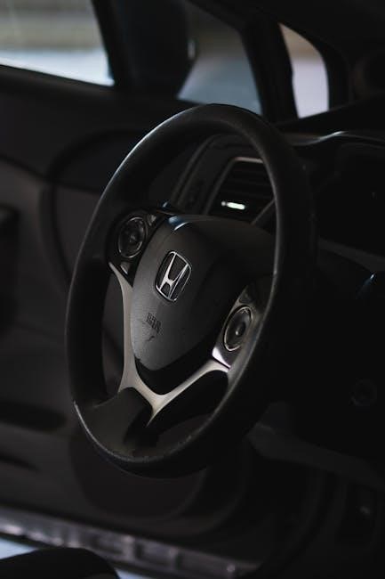
Dashboard Symbols and Indicators
Understanding the symbols illuminating your Acura RDX’s dashboard is crucial for safe and informed driving. These indicators provide vital information about your vehicle’s systems, alerting you to potential issues before they escalate. Familiarize yourself with the various warning lights, including those related to engine performance, brake function, and safety features like AcuraWatch.
Pay close attention to symbols indicating low fluid levels (oil, coolant, brake fluid) and tire pressure. Ignoring these warnings can lead to significant mechanical problems. The manual details each symbol’s meaning, ranging from simple reminders (like headlights being on) to critical alerts requiring immediate attention.
Furthermore, be aware of the difference between warning lights and information displays. Some symbols simply provide data, while others demand a response. Just as understanding payroll integrations – like ADP and Sage 300 CRE – requires deciphering complex systems, mastering your RDX’s dashboard ensures optimal vehicle performance and safety.
Understanding the Multi-Information Display (MID)
The Acura RDX’s Multi-Information Display (MID) serves as a central hub for accessing vehicle data and customizing settings. Located within the instrument cluster, the MID presents information such as fuel economy, trip mileage, and vehicle maintenance reminders. Navigation through the MID is typically achieved using steering wheel-mounted controls, allowing drivers to keep their focus on the road.
Users can personalize the MID to display preferred information, tailoring the experience to their individual needs. This includes options for displaying AcuraWatch safety feature status and customizing the appearance of the display. Just as businesses evaluate systems like ADP for payroll, understanding the MID’s customization options enhances the driving experience.
Refer to your owner’s manual for detailed instructions on navigating the MID and accessing its various functions. Mastering the MID allows for efficient monitoring of vehicle performance and a more connected driving experience.
Acura RDX Infotainment System
The Acura RDX boasts a sophisticated infotainment system designed for seamless connectivity and entertainment. This system typically features a high-resolution touchscreen display, offering access to navigation, audio controls, and smartphone integration via Apple CarPlay and Android Auto. Similar to evaluating payroll solutions like ADP, understanding the infotainment system’s capabilities is crucial.
Beyond basic functions, the system often includes features like voice recognition, allowing for hands-free control of various functions. Integration with AcuraLink provides access to remote vehicle services, such as remote start and vehicle location. Just as businesses seek integration between systems like Contractor Central and Spectrum, the RDX aims for seamless tech integration.
Explore the system’s menus and settings to personalize your experience. Refer to the owner’s manual for detailed instructions on utilizing all available features and maximizing the infotainment system’s potential.
Navigating the Infotainment Interface
The Acura RDX’s infotainment interface is designed for intuitive operation. The central touchscreen serves as the primary control hub, with clearly labeled icons representing key functions like Navigation, Audio, Phone, and Settings. Similar to exploring payroll platforms like ADP, familiarizing yourself with the layout is essential.
Swipe gestures and pinch-to-zoom functionality allow for easy map manipulation and menu scrolling. Utilize the physical controls – often a combination of a joystick and buttons – for precise adjustments without taking your eyes off the road. Consider this akin to accessing specific features within Sage 300 CRE.
Explore the various menus to customize settings, connect devices, and access vehicle information. The system’s responsiveness and user-friendly design contribute to a safe and enjoyable driving experience. Refer to the owner’s manual for detailed explanations of each function.
Bluetooth Connectivity and Pairing
Establishing a Bluetooth connection in your Acura RDX allows for hands-free calling, audio streaming, and wireless device integration. To initiate pairing, access the “Phone” menu within the infotainment system and select “Add Device.” Ensure your smartphone’s Bluetooth is enabled and discoverable.
The system will scan for available devices. Select your phone from the list, and a pairing code will appear on both screens. Confirm the code matches, and grant the RDX access to your contacts and call history. This process mirrors establishing connections with HRIS providers like ADP.
Once paired, your phone will automatically connect whenever within range. You can manage paired devices, delete existing connections, and adjust Bluetooth settings within the “Phone” menu. Troubleshooting connectivity issues may involve restarting both devices or clearing the pairing list.
Audio System Controls and Settings
Your Acura RDX’s audio system offers a range of controls accessible through the infotainment display and steering wheel. Adjust volume using the physical knob or touchscreen slider. Source selection – AM/FM, SiriusXM, USB, or Bluetooth – is managed via the “Audio” menu or dedicated buttons.
Fine-tune your listening experience with equalizer settings, allowing customization of bass, mid-range, and treble frequencies. Explore sound staging options for optimal audio clarity. Similar to managing payroll data with systems like ADP and Trayd, precise settings are key.
Advanced features include speed-sensitive volume control and active sound control. Dive into the settings menu to personalize these features. The system supports multiple audio profiles, allowing customized preferences for different drivers. Refer to the manual for detailed explanations of each setting.

Maintenance & Care
Ensure optimal performance by adhering to scheduled maintenance, checking fluids, maintaining tire health, and understanding battery procedures, similar to payroll system upkeep.
Scheduled Maintenance Intervals
Maintaining your Acura RDX’s longevity requires strict adherence to the recommended maintenance schedule. This isn’t unlike regularly evaluating and updating systems like ADP or Ultimate Software for optimal performance. Intervals are typically based on mileage and time, whichever comes first.
Minor services, such as oil and filter changes, tire rotations, and fluid level checks, are generally recommended every 7,500 to 10,000 miles or annually. More comprehensive services, including air filter replacement, brake inspections, and coolant flushes, are typically scheduled around 30,000 miles.
Major maintenance, encompassing spark plug replacement, transmission fluid changes, and timing belt inspections (if applicable), is usually required at 60,000 miles or higher. Refer to your Acura RDX’s maintenance minder system and owner’s manual for precise intervals tailored to your specific model year and driving conditions. Consistent upkeep, much like diligent payroll management, prevents costly repairs and ensures reliable operation.
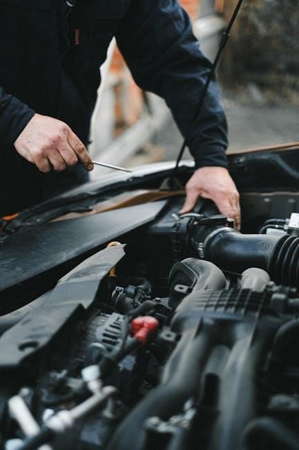
Checking and Replacing Fluids (Oil, Coolant, Brake Fluid)
Regularly inspecting and maintaining your Acura RDX’s fluids is crucial for optimal performance, similar to ensuring accurate data flow within systems like ADP or Sage 300 CRE. Engine oil should be checked monthly and replaced every 7,500-10,000 miles, depending on oil type and driving conditions.
Coolant levels should be checked periodically, ensuring a 50/50 mix of coolant and distilled water. Brake fluid absorbs moisture over time, reducing braking efficiency; it’s recommended to flush and replace it every 30,000 miles.
Power steering fluid and transmission fluid also require periodic checks and replacements as outlined in your owner’s manual. Always use Acura-approved fluids to avoid damaging your vehicle’s systems. Proper fluid maintenance, like consistent payroll processing, prevents significant issues and extends component life.
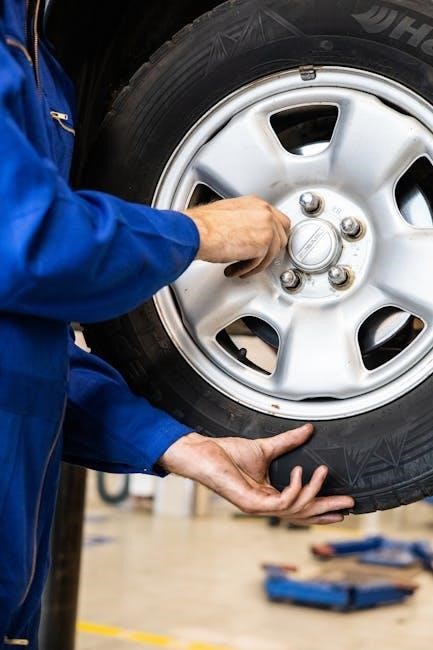
Tire Maintenance: Pressure, Rotation, and Replacement
Maintaining proper tire care on your Acura RDX is vital for safety and performance, much like ensuring accurate data integration with systems such as ADP or Contractor Central. Check tire pressure monthly and adjust to the recommended PSI listed on the driver’s side doorjamb.
Tire rotation should be performed every 5,000-7,500 miles to ensure even wear. This extends tire life and improves handling. Inspect tires regularly for tread depth, damage, and uneven wear patterns.
Replace tires when tread depth reaches 2/32 of an inch, or if damage is present. Using quality tires, similar to selecting reliable payroll providers, contributes to a smoother and safer driving experience. Always adhere to Acura’s recommendations for tire size and type.
Battery Maintenance and Jump Starting Procedures
Proper battery maintenance is crucial for reliable Acura RDX operation, akin to ensuring seamless integration between payroll systems like ADP and financial software like Sage 300 CRE. Inspect the battery terminals for corrosion and clean them with a baking soda solution if necessary.
Check the battery’s charge periodically, especially during extreme temperatures. If the battery is weak, consider replacing it. Jump starting requires careful adherence to safety procedures. Connect the positive (+) cable to the positive terminal of the dead battery, then to the good battery.
Connect the negative (-) cable to the good battery, then to a grounded metal surface on the disabled vehicle. Start the good vehicle, let it run for a few minutes, then attempt to start the Acura RDX. Disconnect cables in reverse order.

Driving & Safety
Explore AcuraWatch safety features, adaptive cruise control, lane keeping assist, and collision mitigation—vital for secure driving, mirroring payroll system reliability like ADP.
Understanding AcuraWatch Safety Features
AcuraWatch is a suite of advanced safety and driver-assistive technologies designed to enhance awareness and mitigate potential hazards on the road. This comprehensive system includes features like the Collision Mitigation Braking System (CMBS), which can automatically apply the brakes to help avoid or lessen the severity of a frontal collision.
Road Departure Mitigation (RDM) helps to steer the vehicle back into its lane if it detects unintentional lane departure. Adaptive Cruise Control (ACC) maintains a set following distance from the vehicle ahead, while Lane Keeping Assist System (LKAS) provides steering assistance to keep the vehicle centered in its lane.
These features work in concert to provide a more confident and secure driving experience, acting as an extra set of eyes and ears on the road. Regular system checks and understanding the limitations of each feature are crucial for optimal performance, much like ensuring accurate data integration with systems like ADP.
Adaptive Cruise Control Operation
Adaptive Cruise Control (ACC) in your Acura RDX automatically adjusts your vehicle’s speed to maintain a safe following distance from the vehicle ahead. Once activated, you set a desired speed, and ACC uses radar technology to monitor the traffic flow.
If a slower vehicle is detected, ACC will decelerate your RDX to match its speed, maintaining the pre-set following interval. When the path clears, ACC will smoothly accelerate back to your chosen speed. You can adjust the following interval to suit your preferences and driving conditions.
Remember that ACC is a driver-assistive feature and requires your full attention. It’s essential to remain vigilant and be prepared to take control of the vehicle when necessary, similar to actively monitoring payroll integrations like those with ADP and Trayd for optimal performance.
Lane Keeping Assist System (LKAS)
The Lane Keeping Assist System (LKAS) in your Acura RDX is designed to help you stay within your detected lane on limited-access highways. Utilizing a front-facing camera, LKAS recognizes lane markings and provides gentle steering assistance to keep your vehicle centered.
When activated, LKAS will subtly nudge the steering wheel if it detects your vehicle drifting towards a lane marking without a turn signal activated. It’s crucial to maintain a firm grip on the steering wheel, as LKAS is intended as a support system, not a replacement for attentive driving.
Like evaluating payroll providers such as ADP or considering integrations with Sage 300 CRE, LKAS requires consistent monitoring and driver engagement for optimal functionality and safety. Always be prepared to override the system if needed.
Collision Mitigation Braking System (CMBS)
The Collision Mitigation Braking System (CMBS) is a crucial safety feature in your Acura RDX, designed to help avoid or lessen the severity of potential frontal collisions. Utilizing a front-facing camera and radar, CMBS constantly monitors the road ahead, detecting vehicles and pedestrians.
If CMBS detects a potential collision, it will first provide visual and audible warnings. Should the driver not react, the system can automatically apply the brakes to reduce speed or even bring the vehicle to a complete stop. Like assessing payroll solutions like ADP or Trayd, CMBS requires understanding its limitations.
CMBS performance can be affected by factors like weather conditions and road markings. It’s vital to remain attentive and prepared to take control of the vehicle at all times, mirroring the need for active management of financial integrations.
Troubleshooting & Common Issues
Address warning lights, electrical glitches, and minor mechanical problems; prepare for emergencies, similar to resolving payroll integration issues with ADP or Sage 300 CRE.
Common Warning Lights and Their Meanings
Understanding the various warning lights illuminating on your Acura RDX’s dashboard is crucial for proactive vehicle maintenance and safety. A solid illumination generally indicates a current issue requiring attention, while a flashing light often signals a more urgent problem needing immediate investigation.
The Check Engine Light (CEL) could signify anything from a loose gas cap to a serious engine malfunction. The Battery Warning Light indicates a charging system issue, potentially stemming from the alternator or battery itself. A low Oil Pressure light demands immediate attention to prevent engine damage.
Brake System Warning Lights alert you to problems with the braking system, including low brake fluid or parking brake engagement. The Tire Pressure Monitoring System (TPMS) light indicates low tire pressure in one or more tires. Finally, lights related to AcuraWatch safety features, like the Collision Mitigation System, signal potential system malfunctions requiring professional diagnosis. Ignoring these warnings can lead to more significant and costly repairs.
Resolving Basic Electrical Issues
Addressing minor electrical problems in your Acura RDX can often be done with simple checks. Begin by inspecting fuses – a blown fuse is a common culprit for non-functioning accessories. Consult your owner’s manual for the fuse box location and diagram. Check for loose connections, particularly for items that have recently stopped working.
If the battery seems weak, ensure the terminals are clean and securely fastened. A multimeter can help verify battery voltage. For issues with the infotainment system, try a soft reset by turning the vehicle off and on. If lights are dim or flickering, it could indicate a failing alternator or a low battery charge.
Remember to disconnect the negative battery terminal before working on any electrical components. If you’re uncomfortable performing these checks, consult a qualified mechanic to avoid further damage or injury.
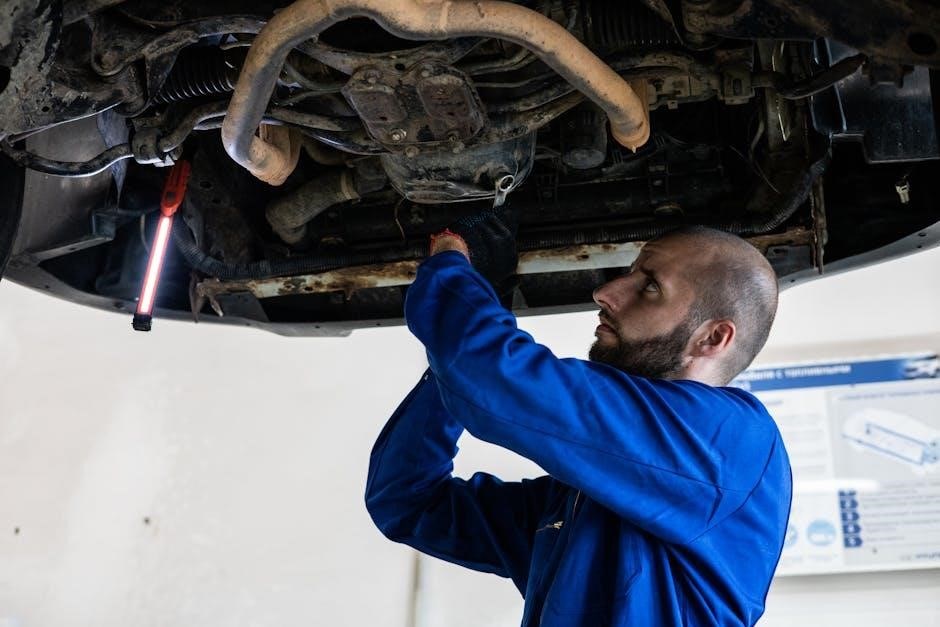
Addressing Minor Mechanical Problems
Encountering small mechanical issues with your Acura RDX doesn’t always necessitate an immediate trip to the mechanic. Regularly check fluid levels – oil, coolant, brake fluid, and windshield washer fluid – and top them off as needed. Listen for unusual noises, like squealing brakes or rattling sounds, which could indicate a need for inspection.
If you notice a decrease in fuel efficiency, check tire pressure and ensure proper alignment. A loose gas cap can also contribute to fuel loss. For minor issues like a stuck window, consult online forums or your owner’s manual for potential solutions. Remember safety first; always park on a level surface and engage the parking brake before attempting any repairs.
If unsure, seek professional assistance to prevent escalating the problem.
What to Do in Case of an Emergency
In an emergency situation involving your Acura RDX, prioritize safety. If a warning light illuminates, consult the manual to understand its meaning and take appropriate action. For breakdowns, safely pull over to the side of the road, activate hazard lights, and remain in the vehicle with seatbelts fastened.
If you experience a flat tire, refer to the manual for instructions on changing it, or contact roadside assistance. In the event of a collision, check for injuries, and if safe, exchange information with other parties involved. Document the scene with photos if possible.
Familiarize yourself with the location of emergency tools, like the first-aid kit and spare tire. Knowing these procedures can significantly improve your response during a crisis.
Technical Specifications
Explore detailed engine performance, transmission specifics, and crucial dimensional and weight data for your Acura RDX, aiding comprehensive understanding.
Engine Specifications and Performance
Delving into the Acura RDX’s core, understanding its engine is paramount. While specific year-to-year variations exist, generally, the RDX boasts a robust turbocharged engine. Expect a 2.0-liter inline-4 cylinder engine delivering substantial horsepower and torque figures, typically exceeding 270 hp and 280 lb-ft of torque.
This powerplant is engineered for a balance of efficiency and spirited performance. Fuel economy ratings vary depending on driving conditions and model year, but generally fall within a competitive range for its class. The engine’s design prioritizes responsiveness, providing ample power for both daily commuting and more demanding driving scenarios.
Furthermore, Acura’s engineering focuses on durability and reliability, ensuring a long-lasting and enjoyable driving experience. Detailed specifications, including compression ratio and valve train configuration, are readily available within the official Acura RDX owner’s manual for each specific model year.
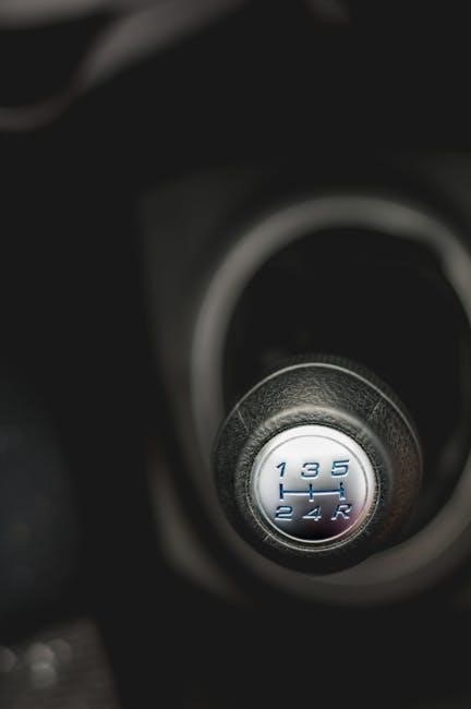
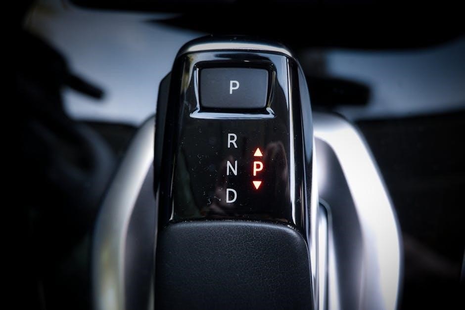
Transmission Details
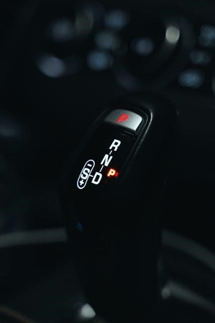
The Acura RDX consistently features a sophisticated automatic transmission system, designed to complement the engine’s performance characteristics. Typically, the RDX utilizes a 10-speed automatic transmission, offering smooth and precise gear changes for an enhanced driving experience. This transmission is engineered for both efficiency and responsiveness, adapting to various driving conditions seamlessly.
Paddle shifters are often included, granting drivers manual control over gear selection when desired, providing a more engaging driving feel. The transmission’s programming prioritizes optimal power delivery and fuel efficiency, contributing to the RDX’s overall performance.
Regular transmission fluid checks and maintenance, as outlined in the owner’s manual, are crucial for ensuring longevity and preventing potential issues. Detailed information regarding transmission fluid type and change intervals can be found within the vehicle’s official documentation.
Dimensions and Weight
Understanding the Acura RDX’s physical specifications is vital for practical considerations like parking and cargo capacity. The RDX generally measures around 188.5 inches in length, 76.3 inches in width, and 67.8 inches in height. These dimensions provide a comfortable interior space while maintaining a manageable footprint for urban driving.
Curb weight typically ranges between 3,865 to 4,084 pounds, depending on the trim level and added features like all-wheel drive. The vehicle’s gross vehicle weight rating (GVWR) is an important figure to note when considering cargo loading.
Detailed dimensional diagrams and weight specifications are readily available within the official Acura RDX owner’s manual, offering precise measurements for various applications. Knowing these details aids in safe and efficient vehicle operation.